Page 119 of 146
Re: "Z" progress.
Posted: Wed Apr 28, 2010 11:26 pm
by pro70z28
Thanks Rapid. I wanted to get this unit finished so I'd be ready for the next sign order. I got the idea of using a clutch master cylinder instead of the porta power pump. But, when I looked at the capacity it looked like that wasn't gonna' work. Then I found a master cylinder (not sure what it fits. Ol' Chevy truck maybe?. I teed both lines together to get the flow I needed & built a frame & linkage out of some of the scrap in that 5 gal. bucket that I just knew I'd use some day. All that's left is to build a shroud for the pump assembly so I don't damage it throwin' stuff under the bench.
http://www.youtube.com/watch?v=GpUO2KGQdGQ
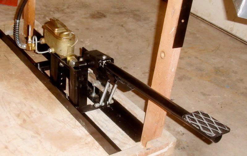
It's not fast, fast but it works and it's hands free.
Re: "Z" progress.
Posted: Thu Apr 29, 2010 11:07 am
by Mr. Jean
Re: "Z" progress.
Posted: Thu Apr 29, 2010 11:54 am
by WildcatOne
Absolutely amazing, ProZ. That's not fast??? I'd like to see a fast one! Cheers, WC1

Re: "Z" progress.
Posted: Sun May 02, 2010 5:09 pm
by jim sanders

nice use of stuff Gary
Re: "Z" progress.
Posted: Sun May 09, 2010 7:38 pm
by pro70z28
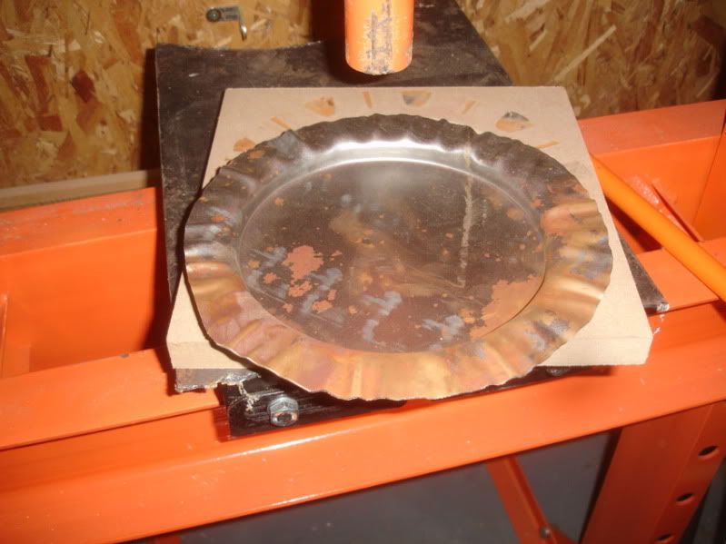
I changed up the design of the firewall some. The change affected the shape of the intercooler flange wells. I decided to stamp the parts, I guess mainly because I wanted to give stamping a try.
I cut dies out of 3/4" MDF board & stamped the sheet metal on the press.
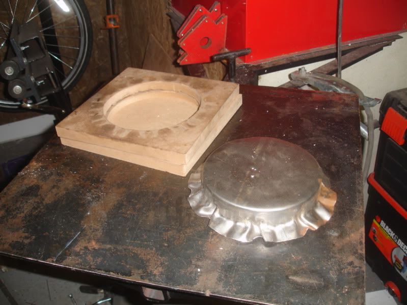
then I rough trimmed the parts.
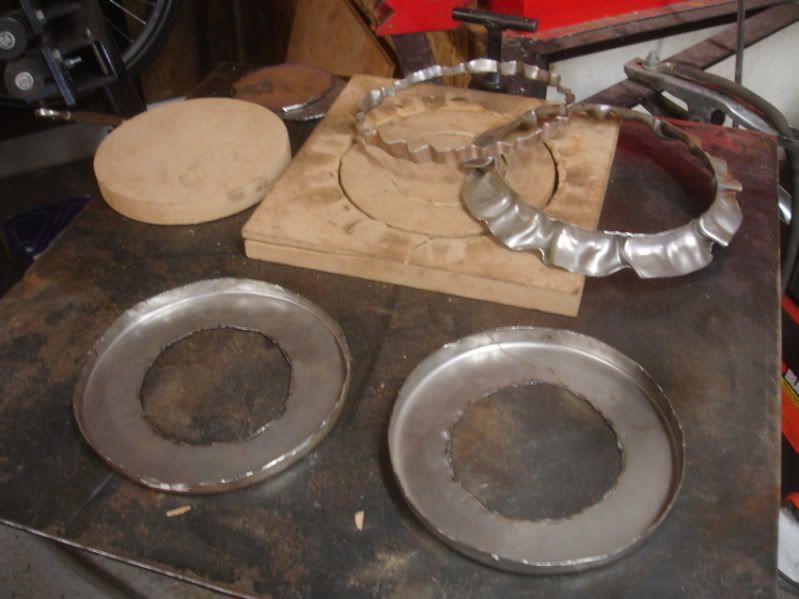
cleaned them up
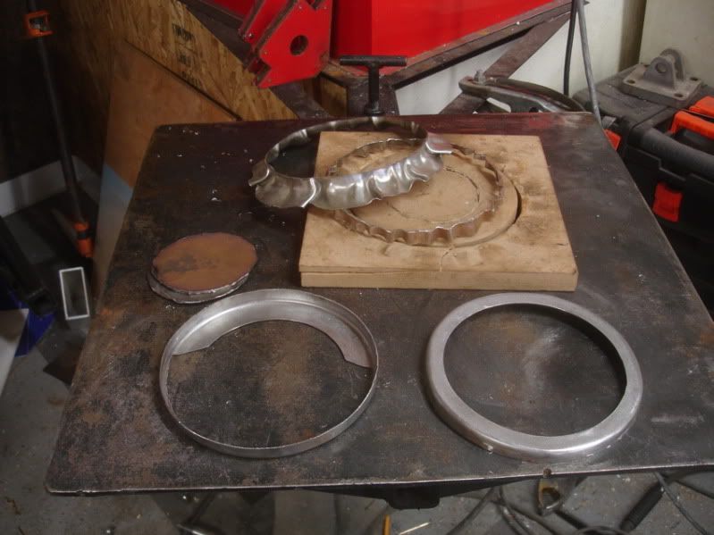
Welded the front & back halves together
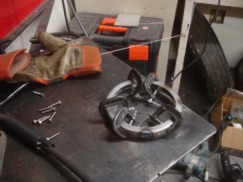
Once I had the tube flanges where I wanted them I welded them together.
Re: "Z" progress.
Posted: Sun May 09, 2010 8:00 pm
by pro70z28
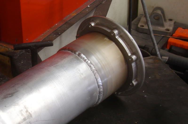
Sorry I got carried away on the project & by the time I remembered to take pictures I had the outlet tube firewall sheet metal done.
This is the firewall before...
and with the intercooler tubes part of the sheet metal in place.
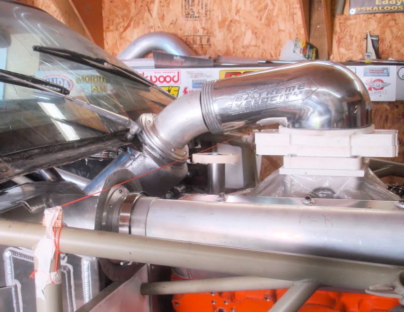
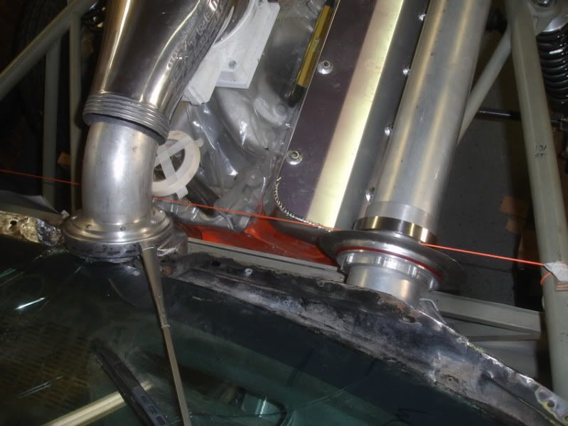
The inlet side is just a simple pie plate deal that will be trimmed & welded into the firewall eventually.
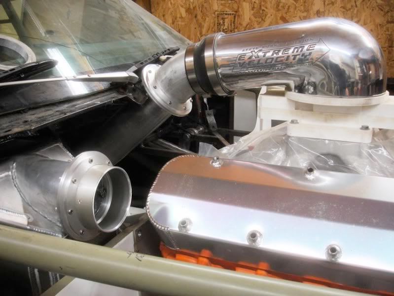
The outlet side was a little more complicated. I didn't want to run the plumbing off to the side (the way it's usually done). I wanted the carb hat facing straight back. Also, the engine is set back about 4" from the stock location. So, the 4" inlet tube has about 3/8" clearance between the windshield and about 1" clearance for the distributor. It's all pretty close but it fits. . The "through the firewall sheet metal'' for the inlet tube ended up looking sorta like shoving the flange through a hefty hefty trash bag.

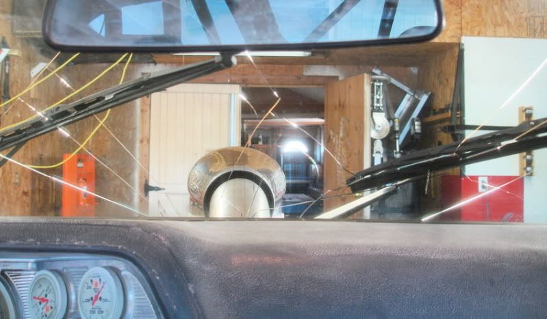
...and here's what it looks like from "the office".
Re: "Z" progress.
Posted: Sun May 09, 2010 8:11 pm
by draglist
Awesome, Gary. It just looks amazing. bp
Re: "Z" progress.
Posted: Mon May 10, 2010 12:04 am
by Mrs. Stimpy
gary I was thinking could you rig a encentric with a shaft up to drive your plunger for your hydraulic sign cutter ??? with a gear down box and a electric motor on switch so your leg don't get tired .
Re: "Z" progress.
Posted: Mon May 10, 2010 8:42 am
by pro70z28
I could, the corner rounder is supposed to be mechanically driven. But this set-up is compact, doesn't take up much room & the foot pedal doesn't take much effort. I have a pretty long pedal arm on it.
Re: "Z" progress.
Posted: Tue May 11, 2010 8:47 am
by pro70z28
Awesome, Gary. It just looks amazing. bp
Thanks BP. Wish I had more time, but ....
forgot I took some shots of the process when I stamped the shallower inlet side.
I cut the 3/4" MDF out on the CNC. I gave one side 1/8" clearance for the metal and the other side the circle press fit into the MDF.
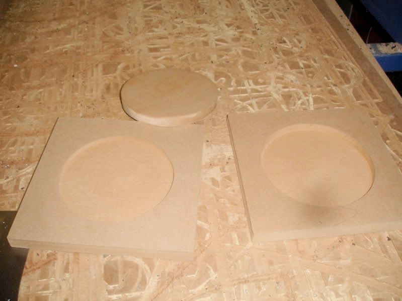
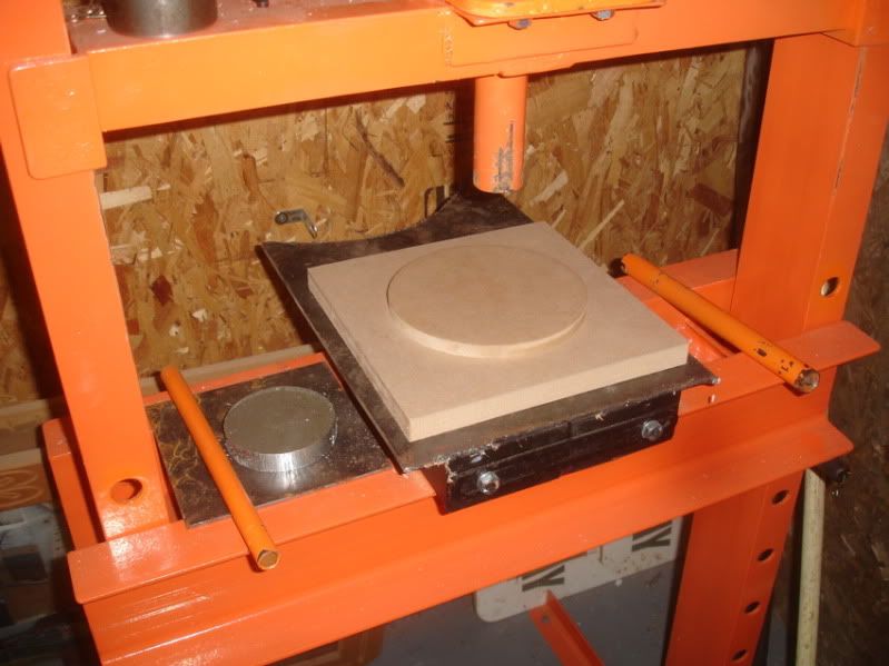
This made the die the right depth (I needed it to be stamped 1/2" deep for the right offset). It also made it easy to register the die halves.
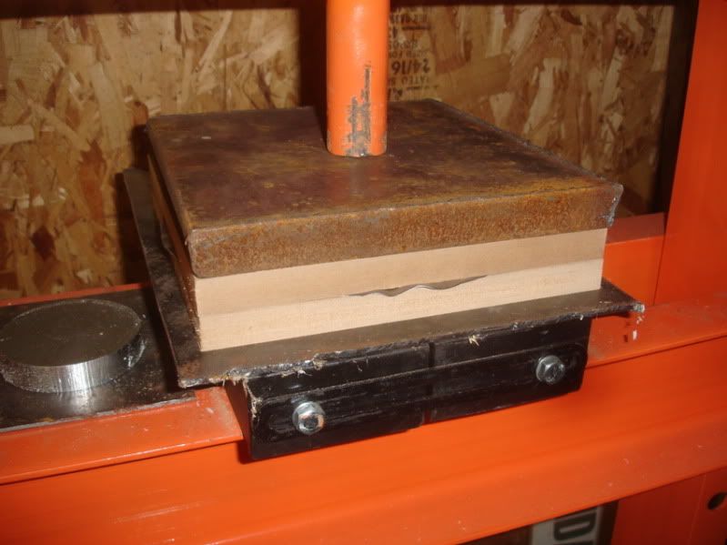
Once out of the press all I had to do was hammer the tucks and it's ready to trim to the firewall. The firewall that doesn't exist yet.